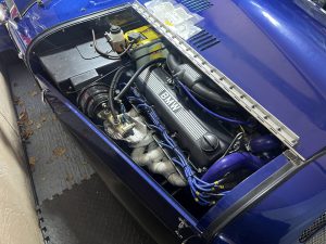
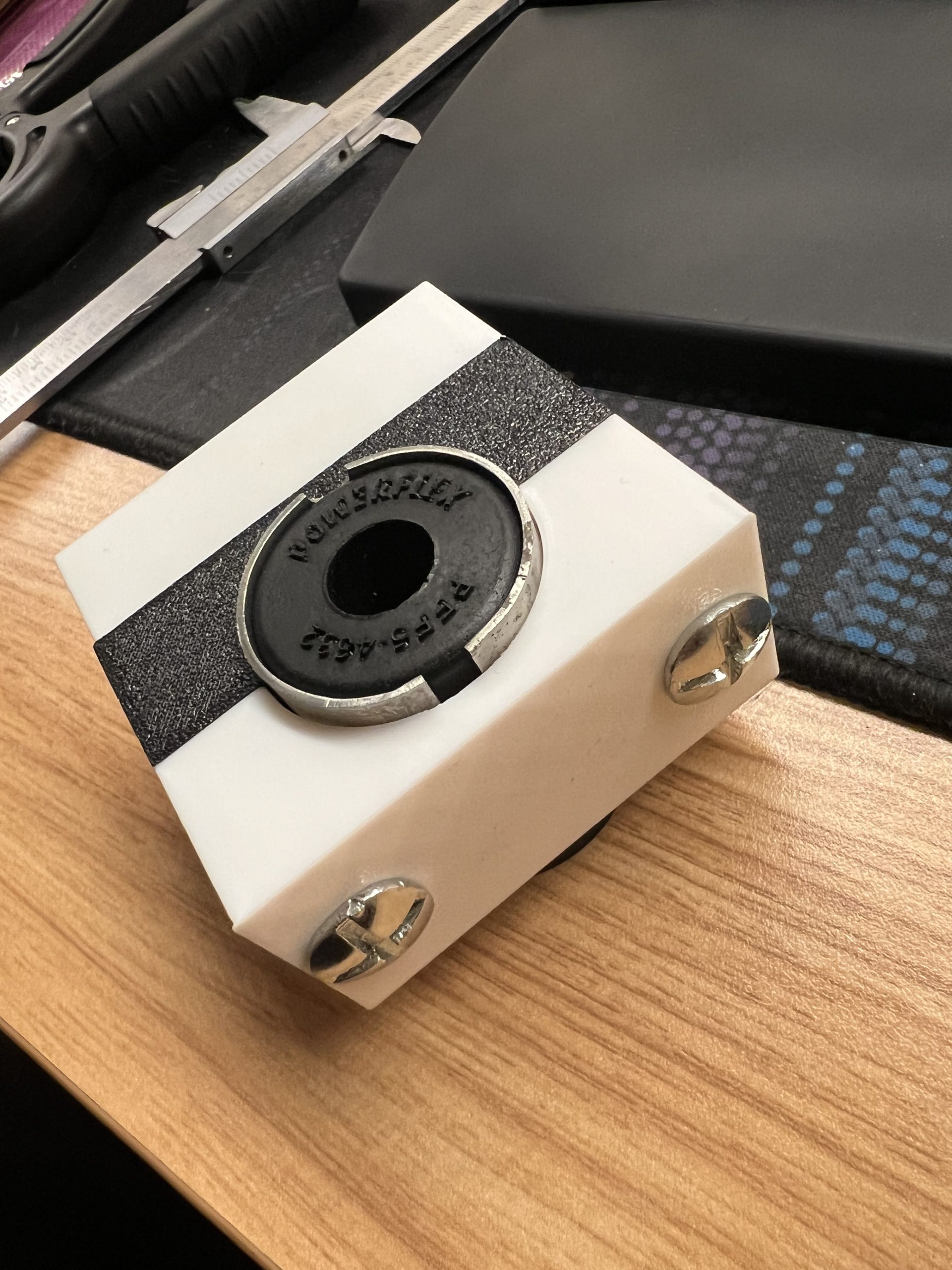
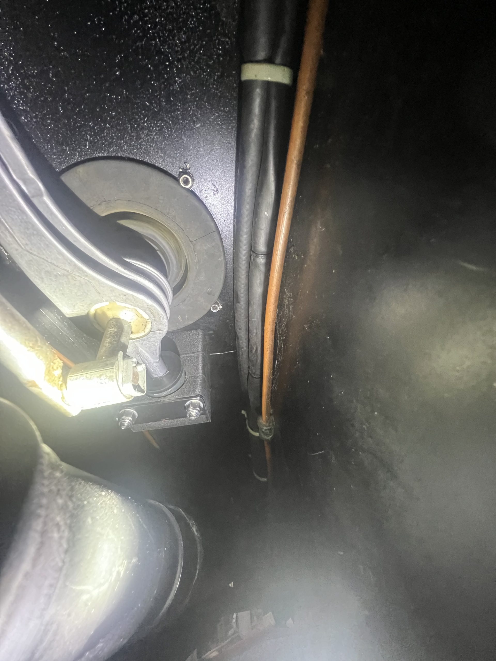
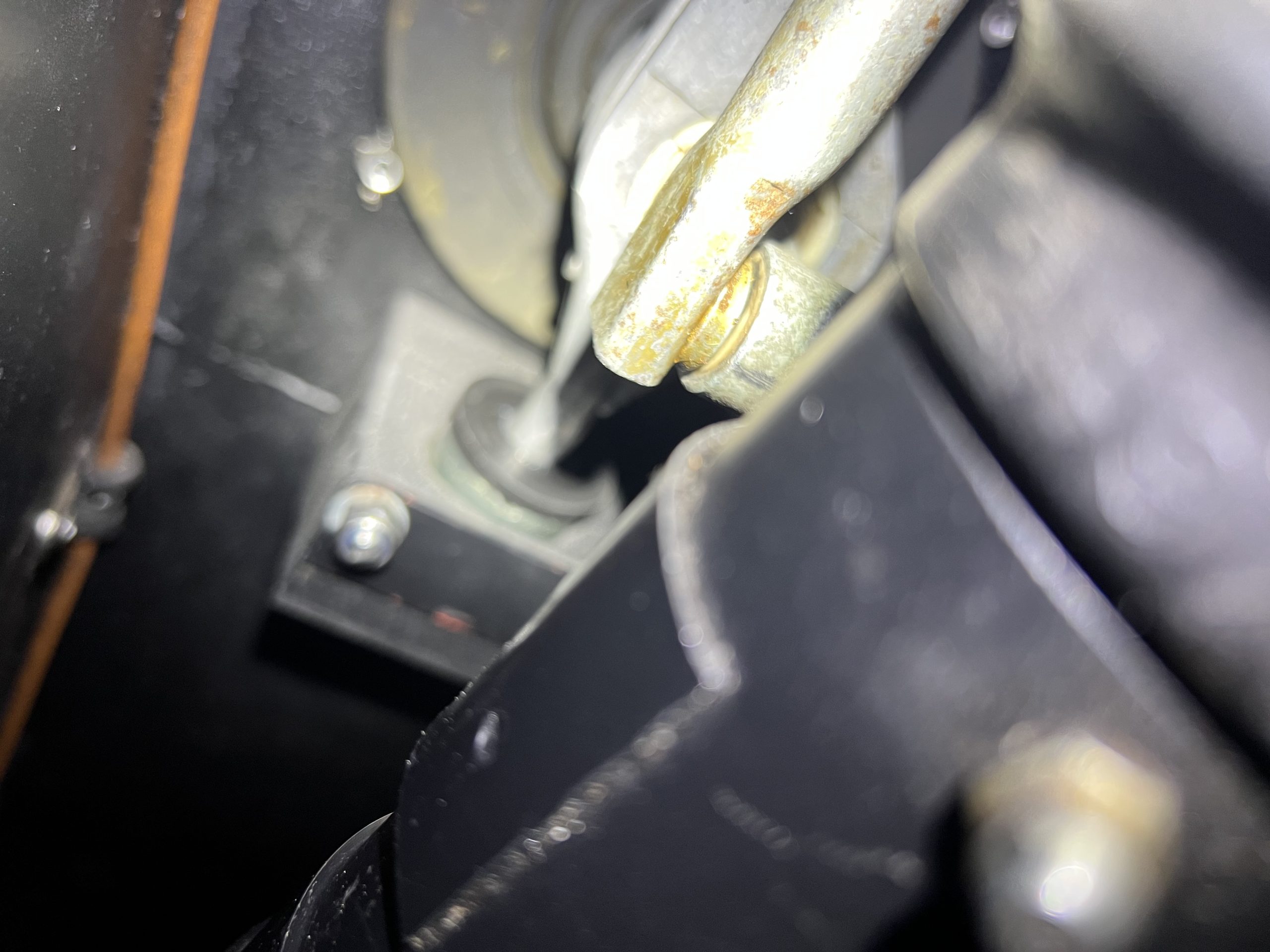
For years a P clip has been holding the gear shift arm up. This was a temporary fix when the first mount method failed. Been keeping a bush from an E36 (BMW P/N: 25111222015) for years as a potential option. Powerflex make a version of this PFF5-4632BLK which I had ordered for the final version. There is a tolerance difference between the OE part and the PowerFlex one – amount 1mm, and the outer casing is not precisely made, but that doesn’t affect the final result.
Spent a good number of days prototyping around 10 different versions in Autodesk Fusion (thank you Autodesk for making this free to use for tinkerers).

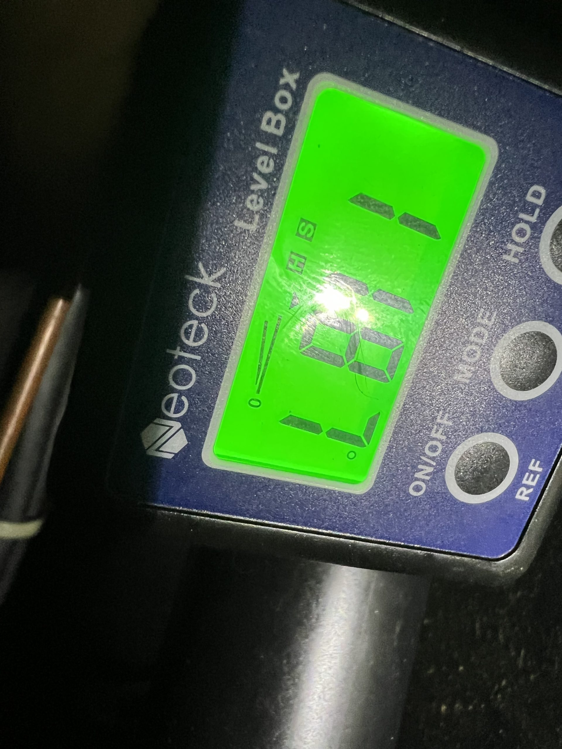
Measured the angle difference between the transmission tunnel and the ideal angle of the gear shift arm at 11.87º – rounded this to 11.9º for the final product.
Early prototype with the OE bush
Some prototype progression, extra mounts shown in the middle of the top piece were for the existing mount hole. The wedge shape at the top, which adapts to the angle of the trans tunnel, is a specific height, established by printing a series of 5mm thick spacers. The spacers were inserted/removed until an ideal height was established for the gear stick.
The screws originally went straight through the block, which would have meant they would not be flush with the trans tunnel. A later revision changed the angle to match the 11.9 degrees required and expanded the bottom piece to accommodate this.
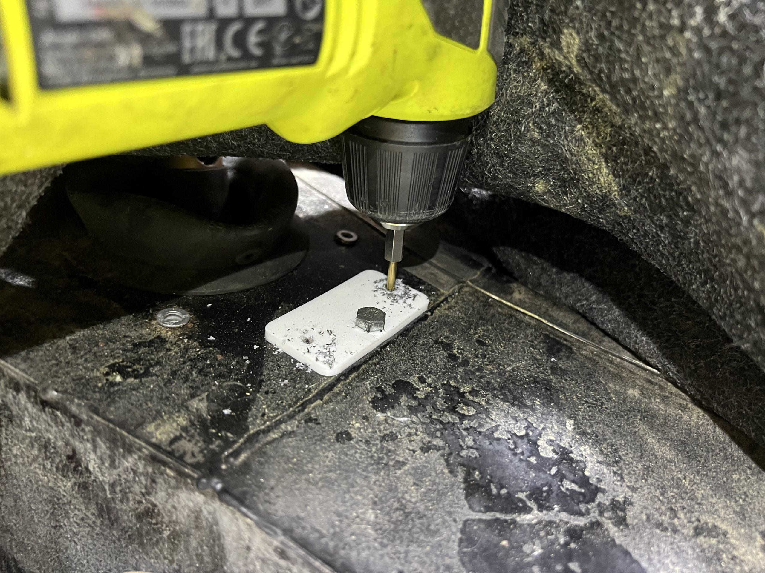
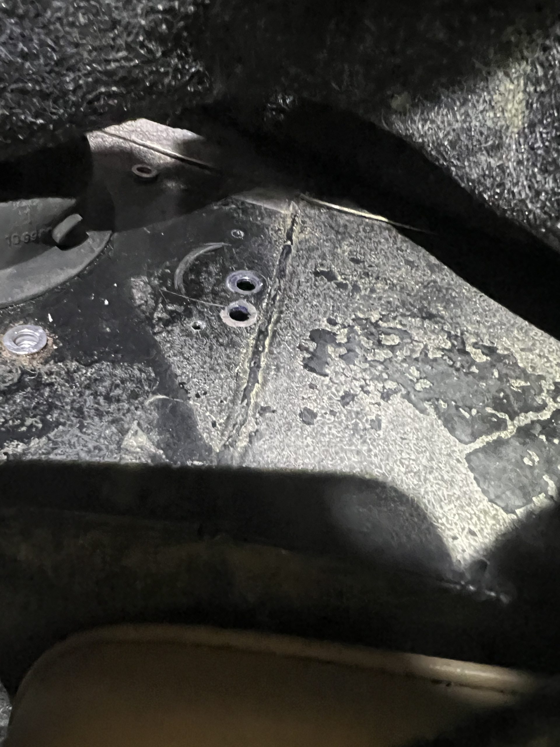
Created a template bolted through an existing mount hole to get the left and right bolt locations where they were needed – easy to model in fusion adding.

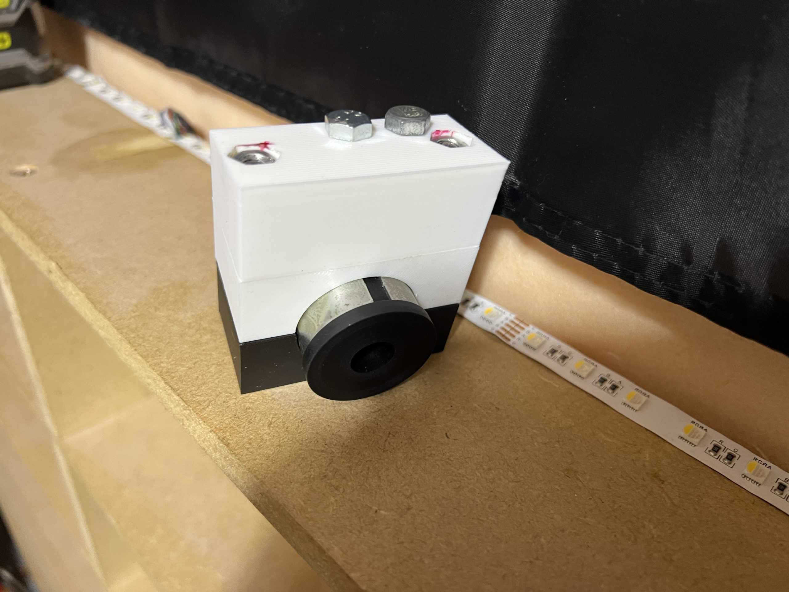
Final prototypes test fitting, not the bush moved forward vs the test assembly off the car – this needed the notches that hole the bush adjusting to get it into the ideal location.
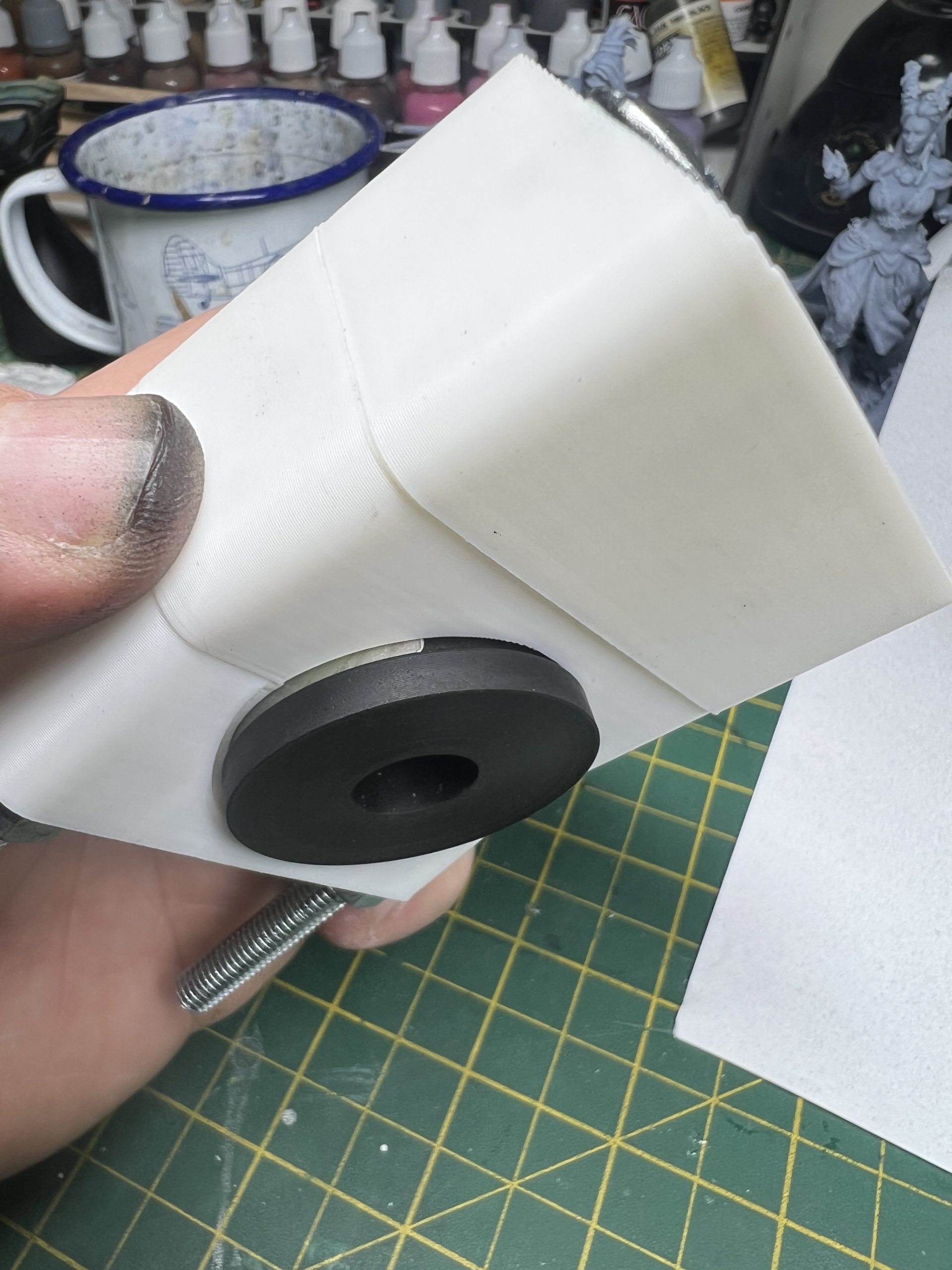
Final prototype
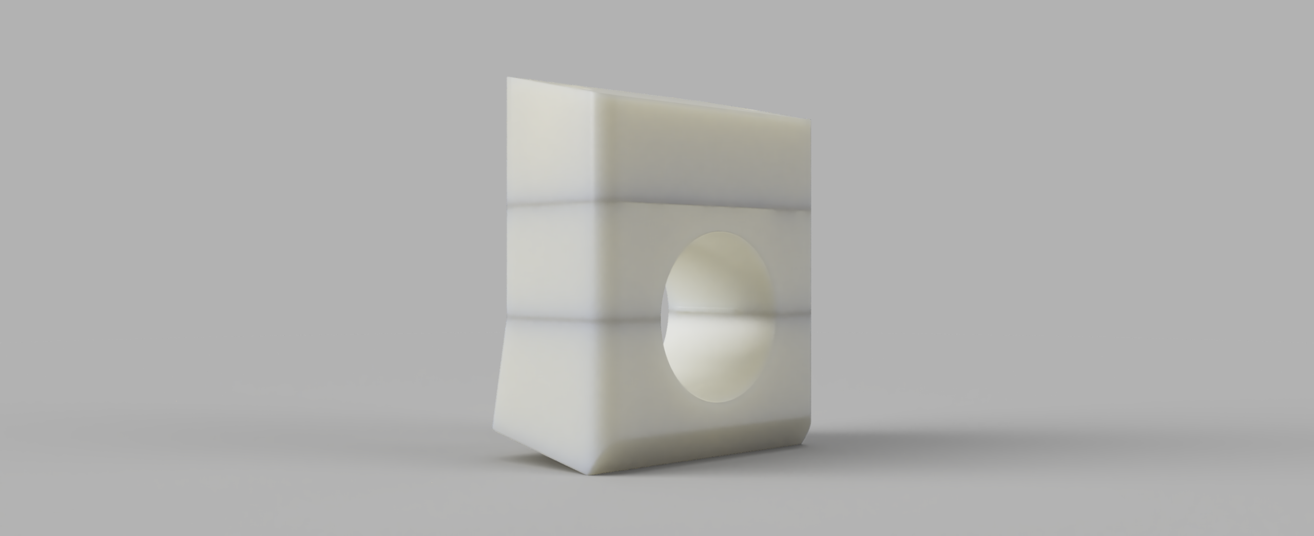
Some renders of the final parts from Fusion


Models exported and prepared in the slicer:

The prototype parts are all PLA – this has a low melt point at 57ºC which is not ideal in a location where lots of engine heat will be passing by. The final part is printed in PA6-CF, which has a melt point of 186ºC and has a resistance to oil.
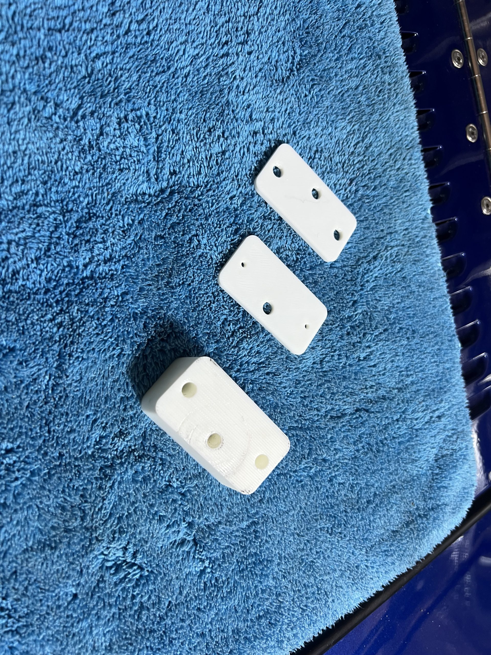
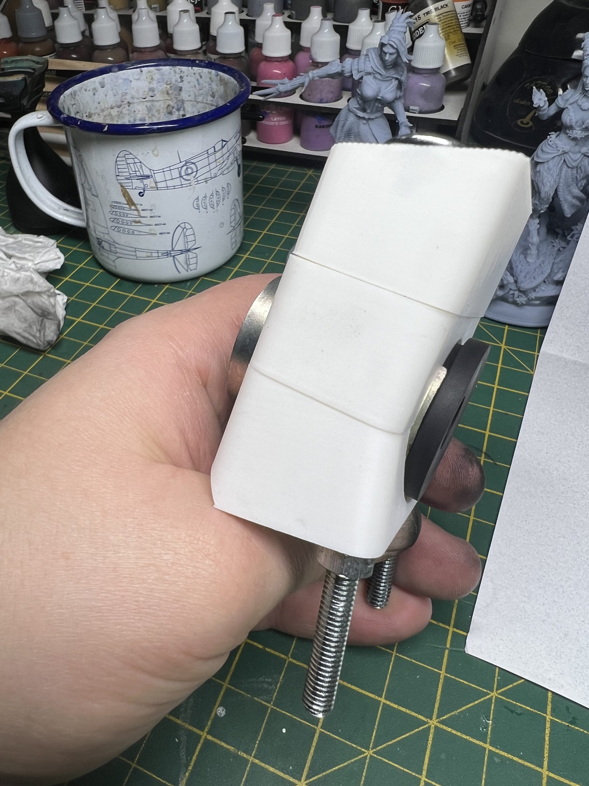
A comparison between PLA (white) and the PA6-CF (black). The PA6-CF expands slightly so I had to hone out the screw holes and run a rotary sander over the bush mount area to take the tiniest amount off.
These were printed with 4 wall loops and 50% infill, which allowed for final fine-tuning of the print. The prototypes were all output on a Bambu Labs A1 mini, the final print on an X1C.

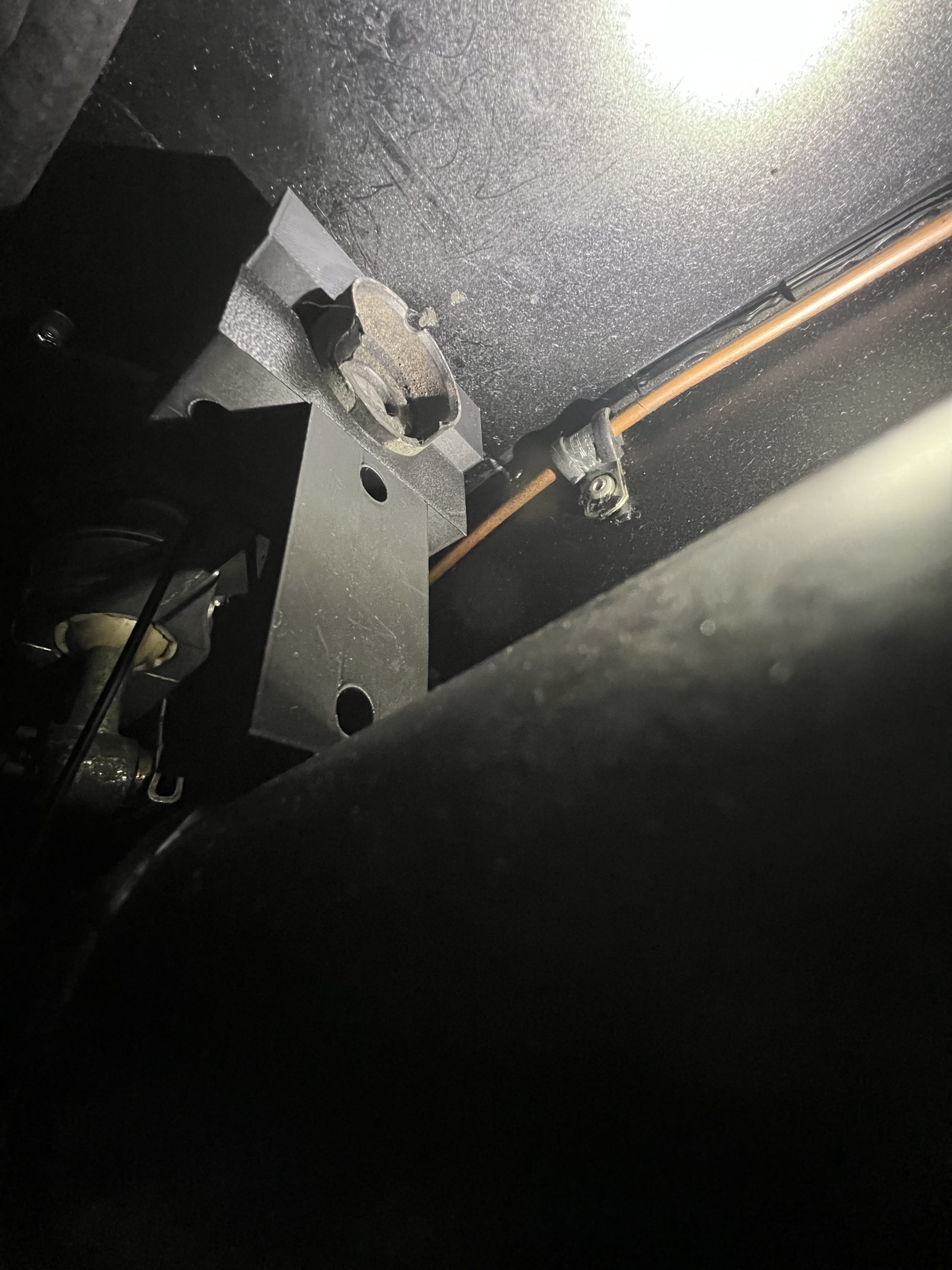
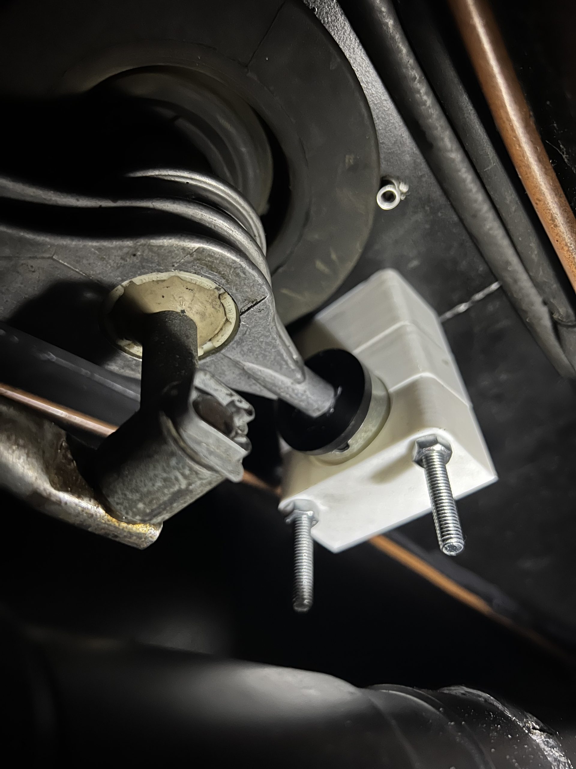
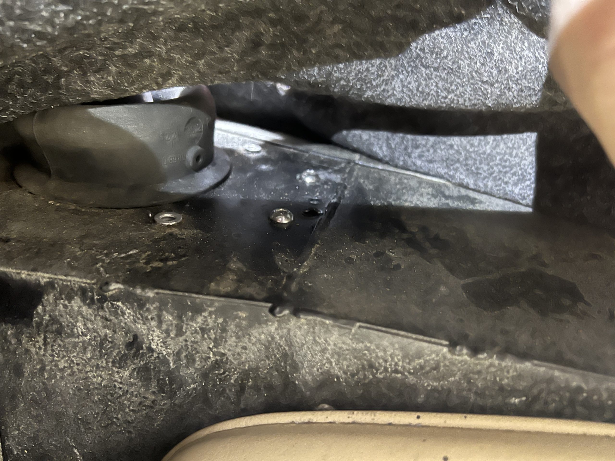
Final installation: cut a metal piece to act as a load spreader on the bottom. The bolts are M6x80mm with button heads as carpet will go back over them, this will minimise the bump.

From the bottom, washers and nylocs to keep everything in place.
Not quite done, after taking the passenger seat out to get the carpet back in, I discovered some surface rust that needs sorting and some slightly bent seat rails, which I’ll be replacing with stronger metal.